Antenna Shootout: Professional Audio (Part 1 - Omnidirectional Antenna)
Introduction
Wireless audio is ubiquitous in all forms of professional audio production, from live concerts to studios. The flexibility and mobility that wireless technology provides is essential. However, many times, deployed wireless audio systems do not perform as expected and require a lot of tweaking, trial-and-error and “dark magic” to coax performance.
In this series, Maven hopes to help you understand and better deploy such systems by investigating a crucial and necessary component in any wireless system: the antenna. The antenna is the interface between the wireless devices to the air, through which Radio Frequency (RF) signals propagate. The antenna’s performance directly affects the efficiency at which RF signals are transmitted and received and the way these signals travel through the environment. Antennas directly impact the overall performance of the wireless system, and using poorer or unsuitable antennas for the application can make it unreliable and not perform as expected.
We will test various Professional Audio wireless antennas in both open-air and indoor environments to illustrate the characteristics of different types of antennas and how they perform in a realistic environment beyond datasheet specifications. In the first part of the series, we will be evaluating and comparing passive omnidirectional antennas for Professional Audio wireless systems, namely,
Audio Technica
Sennheiser
Shure
Wisycom
The measured results from this experiment are based on the physical and electrical conditions each antenna the team at Maven has access to facilitate the experiment. Let us first look at the test setups and the purpose of each test.
Open-Air Test Setup
The first setup evaluates the radiation pattern of each antenna. As the wireless signal strength radiated from an antenna is dependent on the direction of transmission, it is essential to know how it varies in order to determine the performance. The setup consists of a transmitter placed a few meters away from the antenna under test, and the received signal strength is monitored. The antenna is then slowly rotated, and the change in signal strength with respect to the rotation is recorded. This data is represented using a polar plot. As the antennas tested in this part of the series are omnidirectional antennas, it is commonly expected that the signal strength would remain the same in all directions perpendicular to its axis. However, we will see that it may not always be the case. Another thing to note is that as the antenna elements are passive, it does not matter whether the antenna under test is transmitting or receiving, and it will have the same radiation pattern for both cases.


Snippets of Open-Air Test Measurement
Indoor Environment Test Setup
The second test evaluates the coverage of the antenna in an indoor environment. Often, the actual performance of the antenna is very different from the datasheet specifications due to effects such as multipath propagation in indoor environments. This setup consists of the antenna under test being placed at the stage area and connected to a matched transmitter. The signal strength is then measured at various points around the room to give a representative indication of the coverage the antenna provides. The indoor environment test measurement will provide a realistic view of how each antenna performs in actual deployment. Now let’s dive straight into the experimental results.

Indoor Test Measurement Environment (approximately 18m long by 30m wide)

Indoor Test Measurement Layout
For the interested readers, the table below would represent the quality of wireless signal strength (typically illustrated on professional wireless receivers) with its respective colour mapping.

Colour Legend of measured Wireless Coverage Map
Results
Shure UA8


The Shure UA8 dipole antenna exhibits a good omni directional characteristic. Over the entire rotation, the signal strength fluctuated by a maximum of 6 dB. This good performance translates to a very good (dark green) and even coverage of wireless signals in the indoor test.
Shure UA860SWB

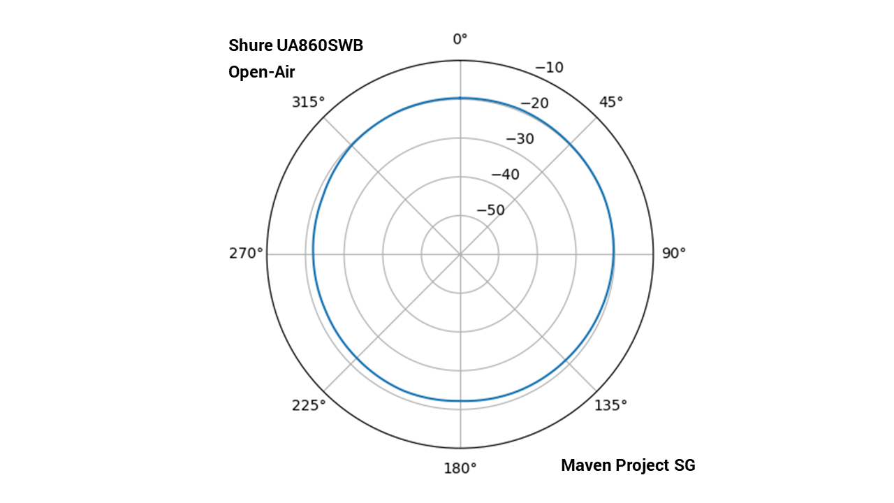

The UA860SWB omnidirectional antenna provides an even more consistent received signal strength from all directions, varying by a maximum of only about 3 dB. It would be expected that this antenna will provide very even coverage of wireless signal in the indoor environment, but it is slightly different from what we see. While the overall signal strength is still good in the test environment, we can see some patches of slightly lower signal strength, due to effects such as multipath fading.
Sennheiser A 1031-U


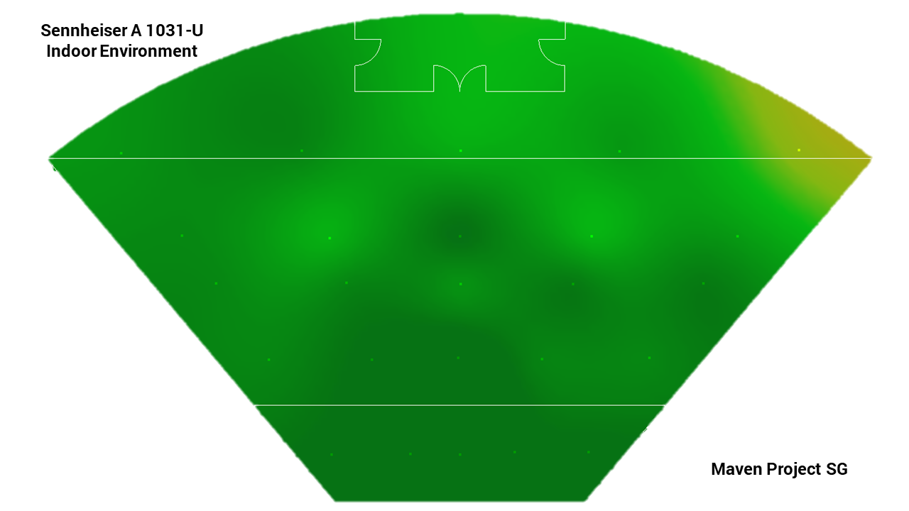
In the Sennheiser A 1031-U, we also see consistent signal strength and good omnidirectional characteristic. As expected, the antenna also provides good indoor coverage, although with a few patches of slightly lower signal strength as observed in the case of Shure’s UA860SWB omnidirectional antenna.
Sennheiser Dipole


The Sennheiser dipole provides a more interesting example. While the highest signal strength is comparative to the other antennas mentioned earlier, it can be inconsistent, dipping almost 10 dB lower in some angles. It means that this particular antenna does not behave as an omnidirectional dipole antenna should, and the overall performance is degraded. This is reflected in the poorer indoor coverage, reaching only fair (yellow) signal strength in some areas.
Audio Technica Dipole


The Audio Technica dipole provides a drastic example of highly varying signal strength depending on the direction. Also, the average signal strength is lower compared to the other antennas. This reduced signal strength may be due to impedance mismatch between the antenna and the characteristic impedance of the RF system. The variance in radiation pattern and lower signal strength results in lower overall coverage, as well as a significant “cold” spot (yellow regions) from the indoor test.
Wisycom ADB


The results from the Wisycom ADB test clearly shows the significance of the multipath effect in an indoor environment. In the Open-Air test, the antenna has the best and most consistent radiation pattern of all the tested omnidirectional antennas and the highest average signal strength. As expected, it has very good and robust indoor coverage. However, there is a very striking spot of reduced signal strength (yellow region) in the middle due to multipath fading effects, reducing its performance.
Conclusion
We have had a quick look at why antennas are a crucial part of your wireless systems and the importance of understanding them. Using two different tests, we have looked at the performance of some omnidirectional antennas in real-world test scenarios. The Open-Air Test examines the radiation pattern of each omnidirectional antenna in open space. The Indoor Environment Test measures the received signal strength corresponding to the physical location of the test site.
The measurements above show how RF signals variate with space; for instance, the RF signal strength is lower in the yellow regions as compared to the green regions. Depending on the deployed wireless system, the drop in signal strength may cause wireless reliability issues. A change in antenna deployment or installed position should be adopted to improve wireless robustness. A common approach in the industry would be to utilise antenna diversity, where the use of 2 antennas can complement the “cold” spots of each antenna (to be cover in the latter part of the series). The team would also like to emphasise that the measurements conducted in this series are based on the current physical and electrical condition each antenna has. In the next part, we will take a look at directional antennas, their characteristics and performance.