Antenna Shootout: Professional Audio (Part 2 - Directional Antenna)
Introduction
In the previous part of this series, we have looked at why antennas are an important part of your wireless system and the performance of some omnidirectional antennas in two different test setups (Open-Air and Indoor Environment). In this part, we will explore directional antennas, such as the Log-Dipole (commonly known as Fin) and Helical antennas, and their performance through the same Open-Air and Indoor Environment tests as mentioned in the previous post. We will also discuss some characteristics of different directional antennas and how they affect the performance.
Directional antennas are the counterpart to omnidirectional antennas. Omnidirectional antennas radiate equally in all directions perpendicular to its axis. Directional antennas radiate preferentially in a single direction. Directional antennas concentrate the Radio Frequency (RF) signal from the transmitter and propagate them in a “beam” on the principal axis. The angle of this “beam” or beamwidth determines how directional an antenna is. One thing to note is that while this “beam” has a much stronger RF signal, the antenna still radiates wireless signal in other directions to some extent, albeit at a much lower level. Also, as the antenna element is a passive device, this focusing effect applies for both transmitting and receiving operation of an antenna; where RF signals within the antenna’s beamwidth would have much higher power than RF signal outside the antenna’s beamwidth.

Antenna Beamwidth
We will test various Professional Audio wireless antennas in both open-air and indoor environments (part 1) to illustrate the characteristics of different types of antennas and how they perform in a realistic environment beyond datasheet specifications. In the second part of the series, we will be evaluating and comparing passive directional antennas for Professional Audio wireless systems, namely,
Audio Technica
Mipro
Professional Wireless
RF Venue
Sennheiser
Shure
Wisycom
The measured results from this experiment are based on the physical and electrical conditions each antenna the team at Maven has access to facilitate the experiment. For the interested readers, the table below would represent the quality of wireless signal strength for the indoor coverage measurement test (typically illustrated on professional wireless receivers) with its respective colour mapping.

Colour Legend of measured Wireless Coverage Map
Results
Let’s move on with the experimental results, starting with the log-dipole antennas.
Audio Technica ATW-A49


The measured radiation pattern of the Audio Technica ATW-A49 shows that it is not an exceptionally directional antenna, with a relatively broad beamwidth (measured 3dB beamwidth at 171°). The signal strength remains high in the forward direction and gradually drops by 10 dB near the back. As there is still differentiable differences between the forward and the backward direction, it still serves well as a directional antenna. This wide beamwidth is reflected in the indoor coverage test, with a very good signal strength coverage throughout the venue, with only a few slightly weaker spots (yellow zone at the top right corner of the auditorium).
Shure PA-805SWB


The Shure PA-805SWB shows a very distinct radiation pattern of a directional antenna, measuring at 101°. In the forward direction, the antenna has the highest signal strength, which then gradually reduces until the half-power or -3dB point in a symmetrical manner. It then drops quickly and remains at a lower signal strength at the back. This antenna has a moderate beamwidth with good rear rejection to prevent unwanted RF noise pick up. From the Indoor Environment test, signal coverage was good, except at the outer edges of the venue, where due to the narrower beamwidth, the signal is slightly lower.
Mipro AT-90W


The Mipro AT-90W has an interesting radiation pattern result. While it also has a high peak signal strength, the peak is also slightly off-axis at 337.5°. The radiation pattern is also not very symmetrical, remaining relatively high throughout and dipping in the rear direction. This results in a relatively even coverage pattern for the Indoor Environment test, while the signal strength is reduced at the right side of the venue due to the off-axis behaviour. There is a significant reduction of signal strength (yellow/orange zone) at the top left edge of the auditorium; this phenomenon is caused by indoor multipath fading effect.
Sennheiser A 2003-UHF


The measured half power (3dB) antenna beamwidth of Sennheiser A 2003-UHF is 91°, with its peak slightly off-axis at 325°. The radiation pattern is also not symmetrical where the right-hand axis of the antenna is behaving similar to an omnidirectional antenna with a -30dB rejection dip at the left axis of the antenna. The result from the Open-Air Radiation measurement would translate to a weaker coverage on the left side of the auditorium, especially at the top left edge of the venue.
Wisycom LBN2


The Wisycom LBN2 has a relatively directional radiation pattern compared to the other log-dipole antennas, with an estimated beamwidth of 90°. It is also very symmetrical. Analyzing the Indoor Environment coverage result, there is a region within the beamwidth that has significantly higher signal strength than regions outside the beamwidth, demonstrating the directivity of the antenna. Such characteristic can be very helpful in a noisy RF environment where the antenna can provide high consistent gain to combat against RF noise floor.
Professional Wireless HA-8089


Another type of directional antenna is the helical antenna, and the HA-8089 is one such type. Helical antennas are typically very directional, as observed in the radiation pattern result from the Open-Air test measurement. The signal strength is the highest in the forward direction and quickly drops off, resulting in a narrow -3 dB beamwidth of 61°. One thing to note is that at 90 degrees from the forward axis in either direction, there is a significant dip in signal strength, known as the “null” of the antenna. The coverage pattern shows a very distinct difference in the zone where there is a much higher signal strength and a sharp drop in signal strength outside that zone.
Professional Wireless HA-8091


The HA-8091 shows a very similar radiation pattern as the HA-8089, just with a slightly wider beamwidth, and a more symmetrical radiation characteristic. There is also an absence of a significant null at 90° from the forward direction compared to the HA-8089. The coverage pattern of the HA-8091 also shows a distinct zone of much higher signal strength in the beamwidth. Compared to the HA-8089, the HA-8091 has a much more even and slightly higher signal strength in the areas outside the beamwidth due to its wider antenna beamwidth.
RF Venue CP Beam


The CP Beam is also quite directional comparing to the antennas listed in this part of the experiment, with a narrow beamwidth of 73°. Compared to the other directional antennas, it has the highest signal rejection in the backwards direction of more than 20 dB relative to the peak. This narrow beamwidth results in a distinct region of high signal strength in the coverage pattern. The high rear rejection makes the antenna system less prone to multipath effects, and a more consistent coverage pattern with lesser fluctuations.
RF Venue Diversity Fin


The RF Venue Diversity Fin is a unique entry for this experiment. It is essentially two antenna elements placed in the same location, namely, a log-dipole antenna (LDPA) that is vertically polarized, and a dipole antenna (Whip) that is horizontally polarized. The Diversity Fin requires two measurements for each of the antenna elements. The LDPA has a relatively wide beamwidth of 149° and is quite symmetrical with a backward rejection of about 10 dB. As expected, it provides good signal strength coverage in the auditorium, similar to other antennas of similar performance. The whip antenna measurement result is somewhat inconsistent. The radiation pattern appears to be quite erratic but still maintains relatively decent signal strength in some directions. It should be noted that while a dipole antenna is omnidirectional, it is only valid in the directions perpendicular to its primary axis. For the case of the dipole whip antenna, the antenna is mounted horizontally, and the measured radiation pattern does not emit good omnidirectional characteristic. The indoor coverage measurement clearly shows this effect, where there is also a central beam of high signal strength, and the signal strength deteriorates significantly outside the beam from the Indoor Environment test.
Discussion
An important characteristic of antennas to highlight at this juncture is that all RF waves have a property called polarization. Simply put, it is the way the electric field moves across space and is generally categorized into two types, linear and circular polarization. These two types are further subdivided into vertical and horizontal for linear polarization, Left-Handed (LHCP) and Right-Handed (RHCP) for circular polarization, summarized in a chart below.

Categorisation on Antenna Polarization
The polarization of the RF wave is determined by the polarization of the antenna, an intrinsic characteristic of the antenna. For instance, a linearly polarized dipole antenna positioned vertically will radiate vertically polarized RF waves.
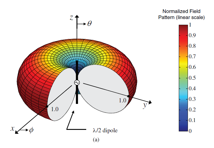
3D illustration of Linear Polarization of a Dipole Antenna - Credits: Antenna Theory Analysis and Design - Constantine A. Balanis
Generally speaking, most antennas with one-dimensional or two-dimensional forms, such as dipoles and log-dipole antennas, are linearly polarized, while helical antennas are circularly polarized. A key takeaway is that each type of antenna is only suited to certain polarizations of RF waves, as shown in the table below.

Signal strength loss for various pairs of transmitting and receiving antenna polarization

Microphone Orientation vs Wireless Power Received
We have also performed an indoor coverage measurement on two differently polarized antennas to illustrate this effect. For a linearly polarized antenna, the Shure PA805SWB mounted vertically along the Z-axis. The Professional Wireless HA-8089 will be used as an example for a circularly polarized antenna. Both antennas will be set to transmit an RF signal, and the coverage pattern will be measured in 2 scenarios. Once, when the receiving dipole (linear polarization) antenna is vertically polarized, and once for the receiving antenna is horizontally polarized.
Linear Polarization: Shure PA805SWB

Shure PA805SWB - Vertical Polarization

Shure PA805SWB - Horizontal Polarization
Circular Polarization: Professional Wireless HA-8089

Professional Wireless HA-8089 - Vertical Polarization

Professional Wireless HA-8089 - Horizontal Polarization
From the measurement results, it is evident that in the case of the PA805SWB, when the receiving antenna is vertically polarized, which is the same as the transmitting antenna, the coverage pattern is excellent, with high signal strength. When the receiving antenna is horizontally polarized, there is a significant drop in the overall signal strength throughout the venue, with some locations even reaching only a fair level of signal strength (yellow/orange zone).
Comparing the above to the HA-8089, the measurement in both cases results in a very similar coverage pattern, with only some slight variation. This is expected as the antenna is circularly polarized, and can receive both vertical and horizontal linearly polarized RF waves.
The astute might wonder why in the case of the PA805SWB with horizontal receiving antenna polarization, the received signal strength is still fairly good (light green), even the theoretical result indicates that there should be almost no received signal. The answer is that in an indoor environment, the transmitted signal can take many possible paths, reflecting off various objects and features in the venue before reaching the receiver. These reflections may result in a slight shift in the polarization of the RF wave, causing the receiver to be able to detect a small portion of the RF signal, given that the venue is small enough.
Omni vs Directional
So far, we have explored the two main categories of antennas, omnidirectional and directional. It might be appropriate at this point to discuss why you might choose between an omnidirectional or a directional antenna for your application. As explored in the previous part, omnidirectional antennas radiate signal equally in all directions and thus would suit well in a use case where a large area needs to be covered. However, this would also mean that signals will travel in unnecessary directions and thus wasting electromagnetic (EM) energy. Additionally, as the transmitted signal is spread evenly in all directions, the effective range can be quite limited. Directional antennas can help with this as it focuses the RF signal into a beam, which might be able to cover the area of interest in some applications. By doing so, the resulting signal strength within the beamwidth is higher, and the effective range can easily be two to three times that of omnidirectional antennas.
One more thing to consider is when using the antenna for receiving wireless signals. There may be cases where even though the signal strength by an omnidirectional antenna is sufficient, you might still want to consider using a directional antenna. As mentioned previously, as the antenna is a passive device, the radiation pattern is the same for both transmit and receive case. Using a directional antenna, the receiver will only capture RF signal from the beam cone of the antenna, while RF signals arriving from outside the beamwidth will be much reduced. This is especially beneficial in a case where there might be significant amounts of RF noise or interfering signals. By only limiting the received signals to the area of interest, the quality of the wireless connection will be improved by reducing the amount of noise received by the antenna despite the fact that the transmit power remains the same.
Conclusion
Thus far, we have covered both directional and omnidirectional antennas but have limited them to only passive designs. In the next part of this series, we will take a look at active antennas.