Antenna Shootout: Professional Audio (Part 3 - Active Antenna)
Introduction
In the previous parts, we have seen how passive directional and omnidirectional antennas perform in a real-world environment through an open-air radiation pattern test and an indoor environment wireless signal coverage test. In this continuation of our series, where we explore the performance of various popular professional audio wireless antennas, the focus will be on active antennas. Unlike passive antennas, active antennas have built-in circuitry to amplify the wireless signal received by the antenna element. This boost allows weaker signals to be received and to travel on longer, lossier coaxial cables ensuring that sufficient signal reaches the receiver. However, this amplification and increased signal strength might not always be beneficial.
Additionally, most professional audio active antennas, if not all, are receive-only. This means that only the received signals are amplified, and the antenna cannot be used to transmit any wireless signals. Due to this constraint, the indoor coverage test method is slightly different from the method used in the previous two parts of the antenna shootout experiment.


Measurement setup
Previously, both passive omnidirectional and directional antennas are functioning as transmitting antennas to facilitate the indoor coverage measurements. As active antennas are only able to function as a receiving antenna, this method would not work. Instead, the team has to utilise the active antenna under test as a receiving antenna to monitor the signal strength of a standard wireless transmitter that is placed at fixed locations around the auditorium. This would give a reception coverage map of the active antenna. It should be noted that as there is uncertainty introduced due to this modification, the results for the active antenna tests should not be directly compared with the results discussed in the previous posts. In all the tests, any antenna that has configurable gain will be set to 0 dB, unless stated otherwise. The open-air radiation pattern test method remains unchanged, as the antenna under test operates as a receiving antenna during the measurement.

Indoor coverage measurement for active antenna
We will test various Professional Audio wireless antennas in both open-air and indoor environments to illustrate the characteristics of different types of antennas and how they perform in a realistic environment beyond datasheet specifications. In the third part of the series, we will be evaluating and comparing active antennas for Professional Audio wireless systems, namely,
AKG
Audio Technica
Shure
The measured results from this experiment are based on the physical and electrical conditions each antenna the team at Maven has access to facilitate the experiment. For the interested readers, the table below would represent the quality of wireless signal strength for the indoor coverage measurement test (typically illustrated on professional wireless receivers) with its respective colour mapping.

Colour Legend of measured Wireless Coverage Map
Results
Audio Technica ATW-A410P


The radiation pattern of the ATW-A410P shows a relatively omnidirectional behaviour, with consistent signal strength in all directions. While the ATW-A410P is not an omnidirectional antenna from the datasheet, this measurement indicates that as a standalone unit not mounted against a wall, it behaves similar to an omnidirectional antenna. In the indoor coverage pattern test, the received signal strength is fair at the top of the auditorium. Interestingly, the ATW-A410P exhibits some directivity characteristic in an indoor environment (standalone), as the measurement shows high signal strength in the middle of the auditorium.
Shure UA874


The Shure UA874 shows a very distinct directional radiation pattern. With peak signal strength in the principal axis, and a beamwidth of about 101 degrees, and low signal strength from the sides and the rear. The indoor coverage is quite good, other than a few significant dips in signal strength due to strong multipath effects.
AKG RA4000 B/EW


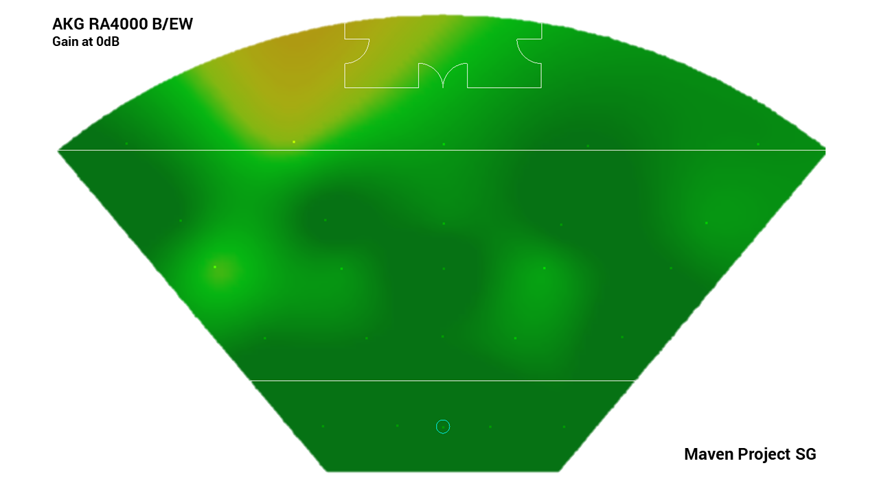
The AKG RA4000 B/EW shows good omnidirectional behaviour, expected of a dipole antenna. It should be noted that as the RA4000 B/EW does not have configurable gain, the overall gain of the antenna is the default, about 17 dB. This results in a signal strength much higher than the other passive dipole antennas. The antenna performed well in the indoor coverage measurement, with most of the venue covered by excellent signal strength (dark green). The measurement also shows that there is a dip in signal strengths causing visible patches lower signal strength (light green/yellow) at the top left corner of the auditorium.
Discussion
While active antennas can provide extra gain to compensate for coaxial cable losses, its use is not suitable for every setup. Other than the fact that active antennas can only receive signals, an excessive gain can result in a signal strength that is too high for the receiver, causing a condition called RF overdrive. When the receiver is overdriven, the signal quality reduces. Another reason is that the signal amplifier in active antennas will amplify all signals within the frequency range of the antenna, including interference and noise. Any amplifier will always degrade the signal-to-noise ratio. The purpose of the amplifier is to prevent the further degradation of the SNR due to the losses elsewhere in the system, such as the coaxial cable.
Another less well-known effect that could happen from the use of any active components, such as an amplifier, is intermodulation distortion. Intermodulation distortion is the mixing of two or more signals at different carrier frequencies due to nonlinearities in the active component. This will result in signals that appear at the sum and differences of any integer multiple of the carrier frequencies.
For instance, with two carrier frequencies, f1and f2, the intermodulation products will appear at mf1nf2, where m and n are integers (...-2, -1, 0, 1, 2…). The peskiest products are the third-order products, where the sum of absolute values of m and n is 3. This is because these products have the highest power, and usually land within the operating frequency range of the system. While some amount of intermodulation occurs in most receivers, the amplifier in an active antenna contributes to it and is especially worse when the signal strength or the gain is large.

3rd-order intermodulation (zoomed in)

Intermodulation products
Conclusion
So far, we have covered most of the popular antennas for professional wireless audio, including omnidirectional and directional antennas in the previous two parts, and looked at the performance of these antennas in both open-air and indoor environments. We have also discussed the characteristics and effects of using different types of antennas. This might seem like a lot to take in for a component that mostly goes unnoticed in the background. In the next and final part of this series, we will perform a roundup of this series and provide a summary of the things to consider when choosing an antenna for your next setup.